Description
1. STRUCTURE OF THE PRODUCT
TABLE 1: STRUCTURE AND FUNCTION DESCRIPTION
Connecting cables between the electronic units are shown in Table 2.
TABLE 2 CONNECTING CABLE LIST
2. PRINCIPLE OF OPERATION
The main parts of the product include main board, LCD, touch screen, 3D ultrasound probe, thermal printer and rechargeable lithium battery.
3D ultrasound probe consists of 2.5 MHz transducer, two step-motor, mechanical transmission mechanism, probe housing and cable. The slave motor drives the transducer to do 120° sector scanning. Main motor drives the motor and transducer to do 180° axial rotating. Then 3D scanning is achieved.
The transducer emits ultrasound wave into the human body with excitation of electric pulse and then receives the reflected signals from the bladder. The urine inside the bladder is low echo area and forms strong reflection at the wall of the bladder. Amplitude discrimination method can easily help to recognize the reflected waves at the bladder anterior and posterior walls and then calculate the distance between the two walls. Cross section area can be calculated with integral calculation method after the scanning is obtained. Then control signal is emitted for 15° rotation of the main monitor and then the scanning for next cross section is initiated. The bladder volume can be calculated with integral calculation method after the scanning of the 12 cross sections is finished.
To guarantee the correct probe location, pre-scanning function is designed to show the ultrasound image of the bladder. Users may adjust the position of probe to make sure that the whole bladder is within the sector scanning area, and then start scanning. A measuring result can be obtained based on these steps.
The product utilizes lithium battery for power supply considering the operation requirements of ward. To ensure that the product can work continuously for enough long time, economical and effective power consumption was thoroughly considered when power management circuit was designed. When the product has not been operated for a long time after switching on, the LCD back light will be switched off automatically. Automatic Power-off function is also designed to effectively utilize battery power
Measuring result output can be achieved through thermal printer or inner memory.
3. UNIT QUALITY INSPECTION
3.1 ACCURACY
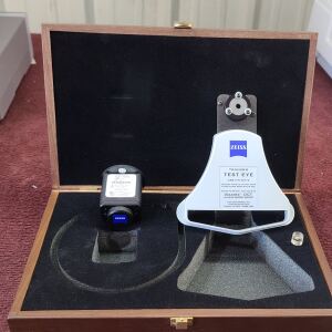
A phantom is used to test the accuracy of volume readings. Inside the phantom is a simulated bladder with a volume mentioned on each unit.
Take 5 scans and check if the highest and lowest one from the 5 readings are within the tolerance.
Caution! Please tune the gain value up to 40dB when being inspected on the phantom, and tune the gain value back down to 20dB after the inspection!
3.2 FUNCTIONS
Test each function in routine operations according to the user’s manual.
In this test item, we focuses on touch screen button, probe button, interface display and printing.
3.3 APPEARANCE
This test item is focused on color, text labeling, scratch marks and spots.
Check whether plastic parts bubble, crack, deform or overflow, whether operational and adjustment mechanisms are flexible and secure, and whether fastening pieces are tightly fastened.
4. COMMON FAULTS AND TROUBLESHOOTING
4.1 POWER SWITCH
Check if the battery is completely plugged into the slot and locked, and check if the battery power is sufficient.
If the above is operated and no failure is detected, please open the housing case following 6. DISASSEMBLY OF THE MAIN UNIT, remove the shielding case and measure power input voltage of the digital board. The normal reading should be 12V±5%
-
If the voltage is abnormal, the problem may occur to the battery interface board and corresponding measures should be taken. The battery interface board connects to the digital board power cable and battery, and is fixed at the back housing case with 4 screws (shown in Fig.4.1). Afterwards, please remove the battery interface board for checking or replacing.
-
If the voltage is normal, the problem may occur on the mainboard. This problem may be judged by substitution method. If problem with the digital part is identified, then the mainboard should be replaced.
4.2 PROBE
A. Physical Probe Issues
-
If the probe cracks and leaks oil, send it back to Service Center or the Manufacturer for further repair or replacement. Do not try to repair on your own.
-
If the probe’s rubber ring deteriorates, breaks, or is missing replace it with a new one. To restore the seal of the rubber ring, secure with a rubber based glue. If you are unable to do so, send it back to the Service Center or Manufacturer for further repair or replacement.
-
If the probe’s motor doesn’t vibrate or work properly send it back to Service Center or the Manufacturer for further repair or replacement. Do not try to repair.
B. Probe Button Malfunction
If there is no response when pressing the probe button:
-
Make sure that the probe and the main unit are well connected and then click “SCAN” key on the main interface. If the probe can work normally, the problem may occur to the probe. Please identify the problem with substitution method and replace the probe when necessary.
-
If the above measure does not work, please open the housing, remove the shielding cover and check probe socket connecting cable. Identify the problem with substitution method and replace the connecting cable when necessary.
-
If the above measures do not work, the problem may occur to main board. Please identify the problem with substitution method and replace the main board when necessary.
C. No Information is displayed when Probe Scans
-
Check if the probe cable is connected well with the probe socket. If the probe is well connected, so scanning with a normal probe. If there is a signal, the problem with the probe can be identified. The probe should be replaced to solve the problem.
-
If the replacing probe still produces no signal, then please open the housing case, remove the shielding case and check the signal cable at the soldered side of the analog board and probe socket connecting cable. If the problem is identified with substitution method, please replace the connecting cable to solve the problem.
-
If procedures 1. and 2. do not solve the problem, please check if the connecting cable (shown in Fig. 8) is well connected and identify the problem with the substitution method. Replace the connecting cable when necessary.
-
If the above-mentioned measures do not work, the problem may be with the main board. Please identify the problem with substitution method and replace the main board if necessary.
D. Probe Scan shows only a vertical line
If you have another probe, use it for test.
-
If system comes back to normal, this indicates that the probe with no image had signal transmission interruption. Please send the probe to the Service Center for repair or cable replacement.
-
If probe is changed and the system still has no image, this indicates that all system failed. Please send your unit and probe together to the Service Center for repair.
-
If you do not have spare probe, please send unit and probe together to the Service Center for repair.
E. Probe Connection Issues
Probe plug has a clip to lock the plug with the socket on the unit. Insertion or removal needs to pull the unlock sleeve to right to low the lock clip. If the plug is dirty, filled with dirt, gel, or oil, it will be hard to connect or remove.
4.3 DISPLAY
A. LCD Calibration
-
Check if there are irrelevant materials at the surrounding area of the screen and clear them off if there is.
-
Calibrate the touch screen for trouble shooting. Touch screen calibration guidance: Switch on the instrument while pressing the probe button and operators will enter screen calibration interface
-
If procedures 1 and 2 do not work, operators may check the connecting cable between the touchscreen control board, the touch screen, and the touchscreen control cable to see if the cables are loose.
-
If the connecting cables are normal, please check the touch screen controller with substitution method. Replace the controller when necessary. Touch screen controller is fixed at the printer cover with 2 screws and can be removed by disassembling the connecting cables and removing the two screws.
-
If replacing controller does not work, the problem may have occurred to the digital part. Operators may identify the problem with substitution method and replace the main board if necessary.