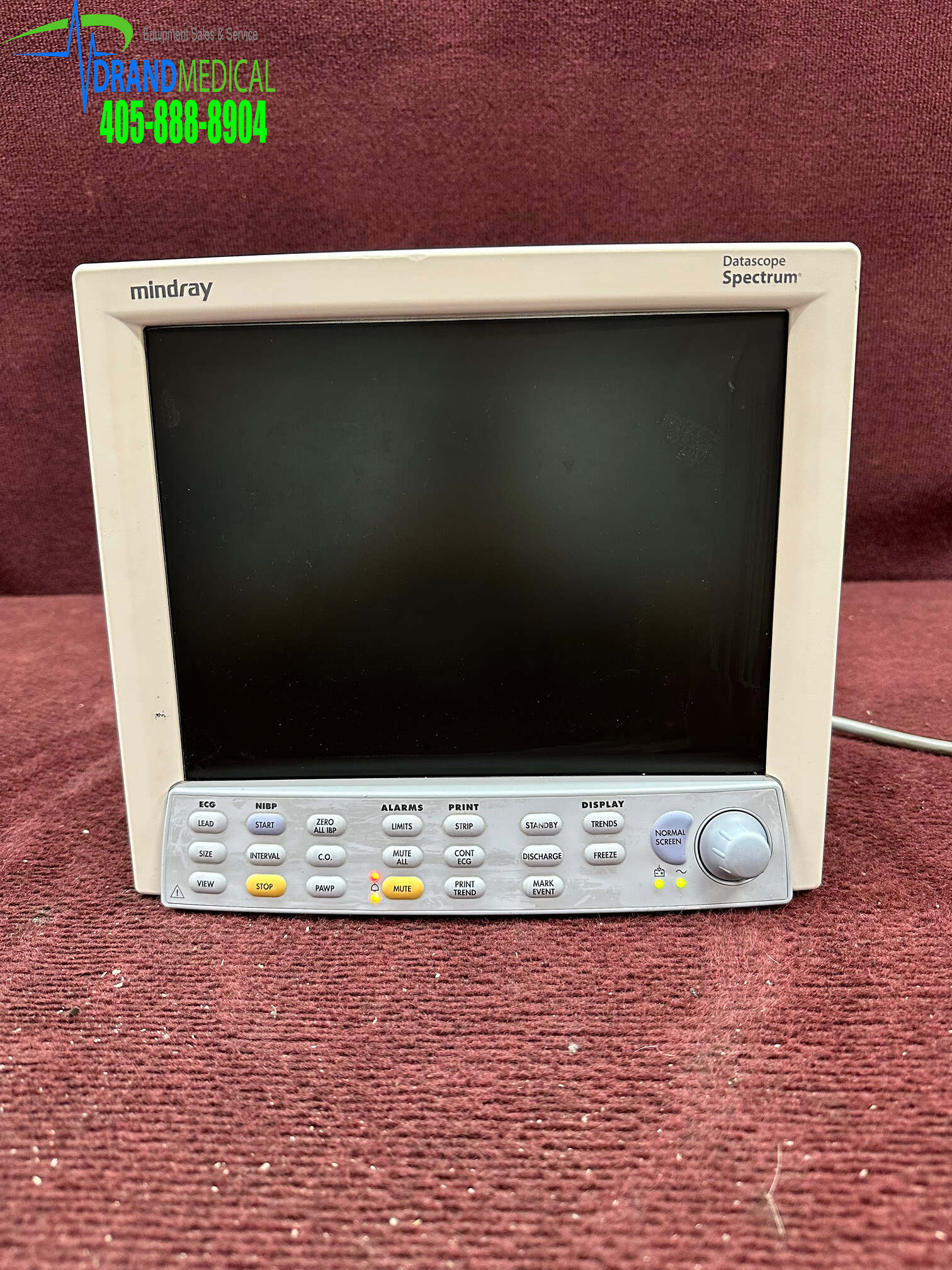
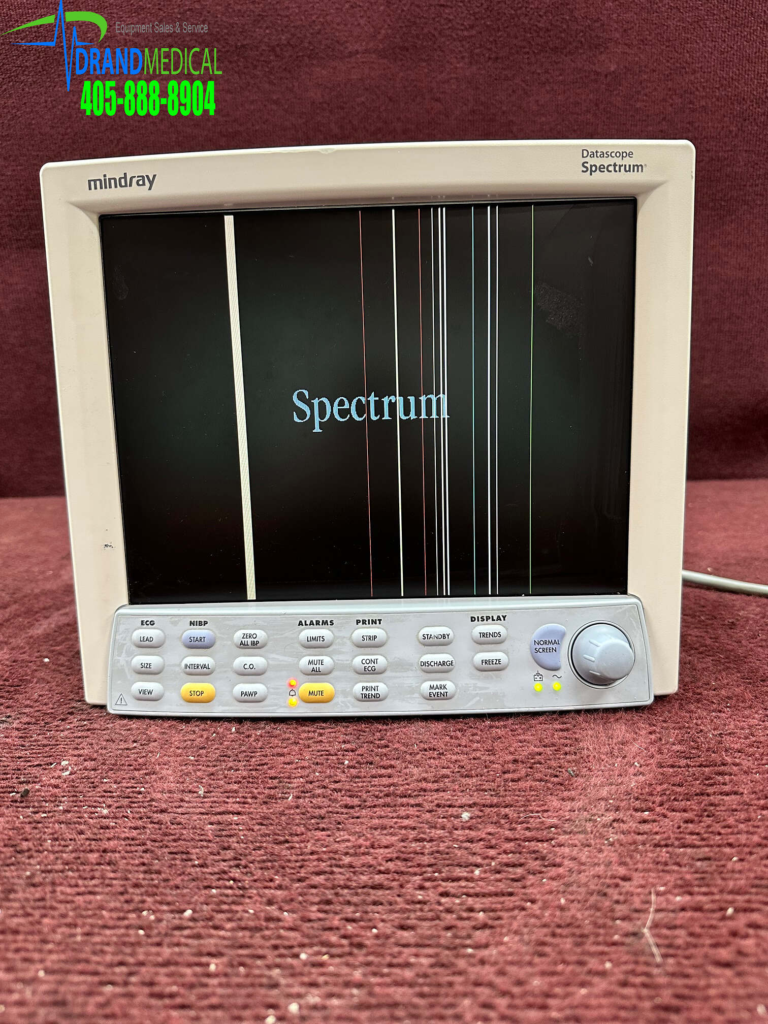
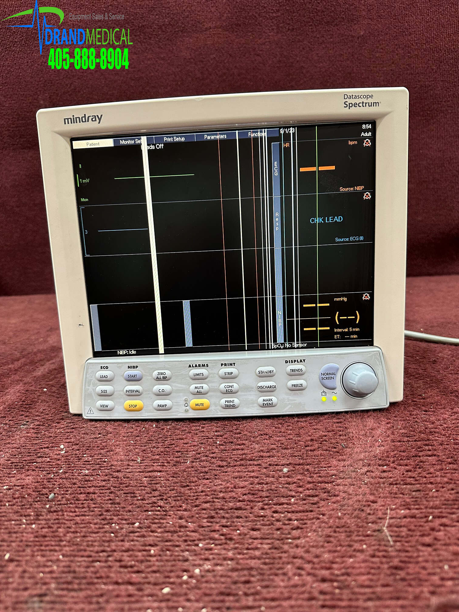
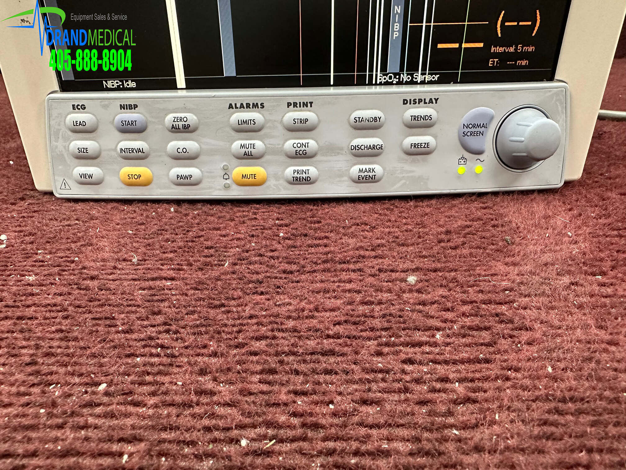
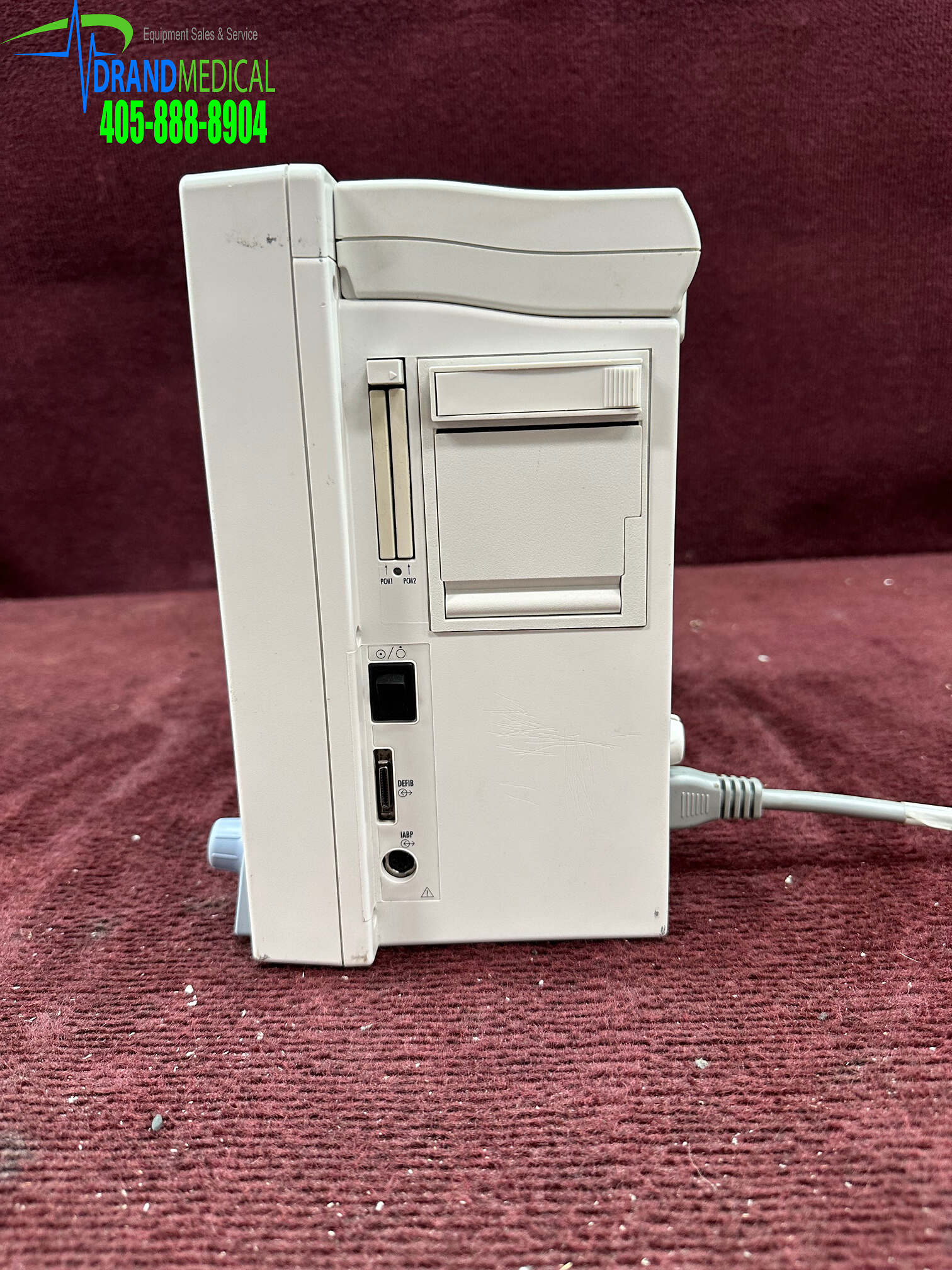
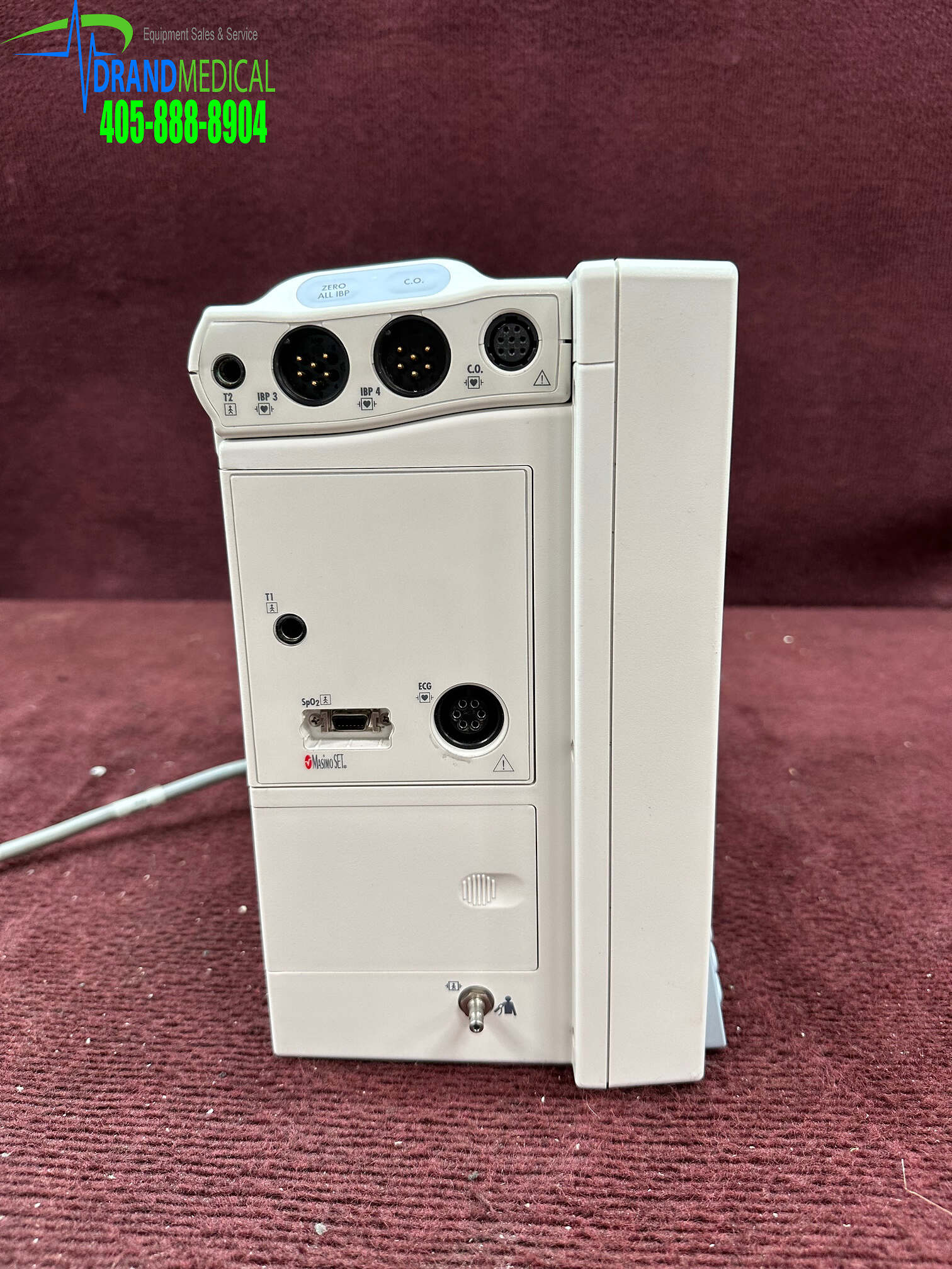
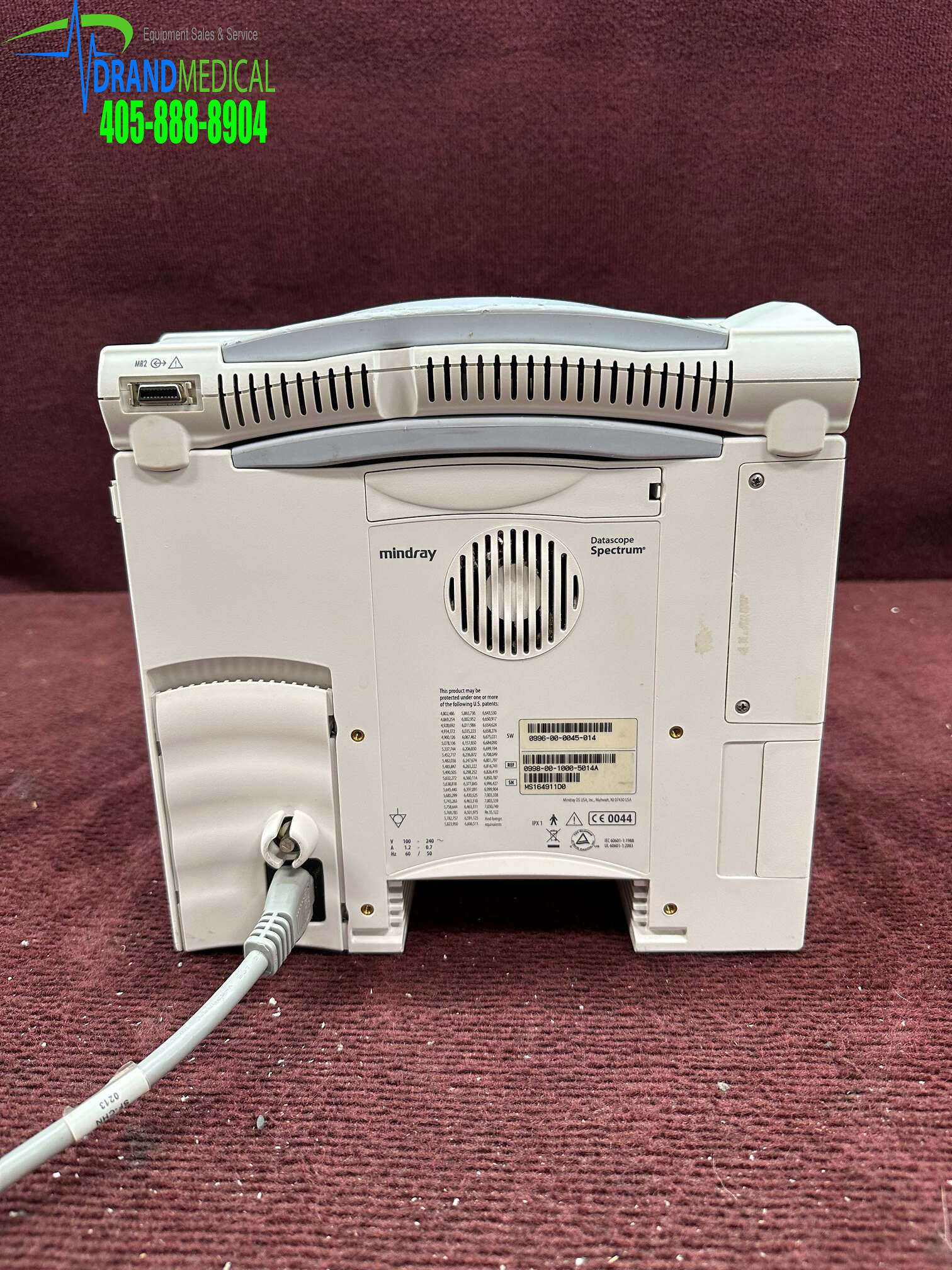
Description
Foreword
The Spectrum/Spectrum OR Service Manual is intended as a guide for technically qualified personnel during repair and calibration procedures. This publication may have been updated to reflect product design changes and/or manual improvements.
Note
Unauthorized servicing may void the remainder of the warranty. Check with the factory or with a local authorized representative to determine the warranty status of a particular instrument.
Warning
The Spectrum/Spectrum OR operates on line voltages. Therefore, an electric shock hazard may exist when the instrument covers are removed. Repair and calibration procedures should only be performed by qualified personnel who proceed with care and follow proper servicing techniques. Warnings are given in various Chapters, as well as in other appropriate locations.
1.1 Introduction
This chapter of the Service Manual provides the necessary technical information to perform repairs to the instrument. The most important prerequisites for effective troubleshooting are through understanding of the instrument functions as well as understanding the theory of operation.
1.2 Safety Precautions
In the event the instrument covers are removed, observe the following warnings and guidelines.
1. Do not short component leads together.
2. The instrument covers must not be removed by other than qualified technical personnel who have received supplementary instructions regarding maintenance of medical equipment or has equivalent experience in this area.
1.3 Troubleshooting Guidelines
1. Identify the problem – Due to the wide variety of potential symptoms certain
problems may be more subtle than others. One approach to troubleshooting is to set up the instrument as described in Chapter 4.0. Following the guidelines of the tests will help determine the problem if one exists.
2. Avoid shorting component leads – During repair procedures, it can become
tempting to make a series of quick measurements. Always turn the power off before connecting and disconnecting the test leads and probes. The accidental shorting of leads can easily stress the components and cause a second failure (aside from the safety risk).
3. Use the Proper equipment – The equipment listed below is suggested to fulfill a
wide range of troubleshooting requirements. It is imperative to use the designated equipment in order to ensure proper results of any and all test procedures.
4. Clean up the repair area – After any repair, especially after any soldering or
desoldering, clean off the repair area with alcohol and a stiff brush. This will remove any residual solder flux, in turn allowing the instrument to return to its original appearance.
1.4 Exchange Programs
An exchange program for certain assemblies in the instrument is available. In many cases replacement of the complete assembly will result in the most expedient repairs.
1.5 Special Tools Required
• DVM
• Digital Mercury Manometer – 0 to 300 mmHg
• Safety Analyzer
• Patient Simulator
• Test Chamber / Dummy Cuff (P/N 0138-00-0001-01 (700 cc) or -03 (500 cc)
• BISx Sensor Simulator (P/N 0454-00-0060)
1.6 Disassembly Instructions
Before disassembling the unit, perform the following:
• Power down the unit and remove the line cord
• Remove all cable assemblies from the left side, right side and rear of the unit
• Remove any batteries that were installed
• Perform all work on a properly grounded ESD workstation
Removal of the Front Housing
1. Place the unit face down on a protective surface.
2. Loosen the screw from the Comm-Port or filler Port. Remove the Comm-Port or filler port from the rear of the unit. Remove the eight screws from the rear of the unit.
3. Turn the unit over and carefully remove the front housing assembly.
4. Disconnect the 80 pin ribbon cable from the J1 of the Display / Keypad board mount in the front housing.
Removal of the TFT Panel
1. Remove Display driver Cable assembly from J5.
2. Remove the Inverter cable assembly from J8 and the display itself.
3. Remove the encoder cable assembly from J4.
4. Remove the Speaker cable assembly from J2.
5. Remove the five screws that secure the Panel board to the front housing and place it to the side. Lift the board up and out.
6. Remove the Keypad cable assembly from J10.
7. Remove the two screws that secure the Speaker holder assembly. Remove speaker assembly.
8. Remove the two screws that secure the High voltage inverter board to the left rail assembly.
9. Remove the high voltage cable assembly from J2 of the inverter board. Place board assembly to the side.
10. Turn the front assembly over and remove the encoder knob from the front.
11. Remove the nut and washer that secures the encoder to the front housing. Push the encoder out the back of the housing and place to the side.
12. Turn the front housing back over.
13. Remove the two standoffs below the display and place to the side.
14. Remove the four screws that secure the Display assembly to the front housing brackets.
15. Slide the Display to the bottom of the front housing and lift the right side past the bracket to remove the display.
Removal of the Module Interface Board
1. Remove the front housing as stated in “Removal of the Front Housing” on page 1-3.
2. Remove the four screws that secure the board to the main frame.
3. Lift board and remove.
Removal of the Main CPU board (Main Frame)
1. Remove the front housing assembly as stated in “Removal of the Front Housing” on page 1-3.
2. Remove the NIBP Pump assembly and bracket as stated in “Removal of the NIBP Pump” on page 1-4.
3. Remove the eight (8) screws that secures the metal shield to the back housing.
4. Remove the Power Supply assembly from the rear of the unit as stated in “Removal of the Power Supply” on page 1-6. Once the Power Supply is removed carefully lift the Main CPU assembly up (about one inch).
5. Disconnect the Recorder cable from J8.
6. Disconnect the connector J13 (power switch).
7. Disconnect the CO2 connector from J 23 (CO2 module)
8. Disconnect the SpO2 connector from the SpO2 board assembly (Masimo® or Nellcor®).
9. Disconnect the connector J203. (Panel board).
10. Carefully lift the CPU board assembly from the back housing.
11. Carefully angle and lift the CPU board assembly from the back housing.
12. Disconnect the connector from J202 and remove the SpO2 assembly.
13. Remove the ten screws that secure the CPU board to the metal frame.
Removal of the NIBP Pump
1. Remove the Front housing assembly as stated in “Removal of the Front Housing” on page 1-3.
2. Disconnect the tubing from the inline pump filter.
3. Disconnect the connector from J8.
4. Remove Pump assembly from holding bracket.
Removal of the NIBP Module.
1. Remove the Front housing assembly as stated in “Removal of the Front Housing” on page 1-3.
2. Remove the NIBP Pump as stated “Removal of the NIBP Pump” on page 1-4.
3. Disconnect the cable from J1.
4. Unfasten the NIBP fitting on the side of the back housing with a 3/8 inch nut driver.
5. Slide the NIBP module from the rear of the unit carefully and remove.
Removal of the Masimo® SpO2 Module
1. Remove the Front Housing assembly as stated “Removal of the Front Housing” on page 1-3.
2. Remove the Main frame assembly as stated “Removal of the Main CPU board (Main Frame)” on page 1-4.
3. Remove the three screws that secure the Masimo SpO2 module to the standoffs.
4. Remove the Cable assembly from J3 of the SpO2 Module.
5. Lift the Masimo SpO2 Module up and remove.
Removal of the CO2 Module
6. Remove the front housing assembly as stated “Removal of the Front Housing” on page 1-3.
7. Remove the Main frame assembly as stated “Removal of the Main CPU board (Main Frame)” on page 1-4.
8. Remove the Patient Connector Panel as stated in “Removal of the Patient Connector Panel” on page 1-5.
9. Remove the four screws that secure the CO2 module to the back housing assembly.
10. Lift the Module up and out of the back housing.
Removal of the Patient Connector Panel
1. Remove the two screws that secure the Patient Connector Panel housing the back housing.
2. Slide the Patient Connector housing toward the back.
3. Swing the housing open and remove the CO2 exhaust tubing, connector and input connector retainer clip (optional).
4. Disconnect the Ribbon cable assembly from the module.
5. Remove the two screws that secure the SpO2 connector to the Panel assembly.
Removal of the Recorder Assembly
1. Open the recorder door and unloosen the captive screws in the rear of the recorder.
2. Slide the recorder from the opening and remove.
Removal of Recorder Interface Board
1. Remove the Front Housing as stated in “Removal of the Front Housing” on page 1-3.
2. Remove the Main frame as stated in “Removal of the Main CPU board (Main Frame)” on page 1-4.
3. Remove the recorder assembly as stated in “Removal of the Recorder Assembly” on page 1-5.
4. Remove the Cable assembly from J3.
5. Remove the two screws and pull the board from the unit.
Removal of the Power Supply
1. Insert a narrow flat blade into each of the four slots and release each tab.
2. Ensure not to damage each tab. Remove the plastic cover.
3. Remove the four screws from the corners of the metal housing.
4. For units with Li-ion batteries only, a control cable is connected to the power
supply as shown in Figure 3-13 on page 3 – 17. The power supply cannot be completely removed without first disconnecting this cable. Slide the power supply out of the rear of the monitor until the control cable connector is exposed.
Disconnect the control cable.
5. Slide the power supply out of the opening and remove.
Removal of the Battery Holder Assembly
1. Be sure the batteries are removed from the battery holder assembly.
2. Remove front housing assembly as stated in “Removal of the Front Housing” on page 1-3.
3. Remove the main frame assembly as stated in “Removal of the Main CPU board (Main Frame)” on page 1-4.
4. Remove CO2 module and CO2 mounting brackets.
5. Remove the five screws that secure the housing to the back housing.
6. Lift and remove the battery holder assembly.
Removal of the 608 MHz Radio Assembly
1. Remove the 2 screws from the radio assembly base.
2. Pull the assembly back from the monitor and place to the side.
