Description
INTRODUCTION
This Express Service manual is intended for use by qualified service personnel for the repair and maintenance of the Expression MRI Patient Monitoring System. This manual contains information regarding the installation, intended use, accessories, and troubleshooting of a fully equipped Expression MRI Patient Monitoring System. The terms “Cart” and “Patient Management Configuration (PMC)” are used throughout this document to refer to the configurations of the Expression MRI Patient Monitoring System. Specific differences between available configurations, where applicable, are noted in the text. Some information in this manual may depict monitoring features that your system does not contain. For information on features and enhancements that are not included in your system, contact Invivo Corporation at (800) 331‐3220 or your Invivo sales representative. For additional information about your accessories, please consult the documentation that accompanied the accessory.
UNPACKING THE SYSTEM
This section provides instructions regarding the unpacking and inspection of the Expression MRI Patient Monitoring System. Remove the system components from the shipping container(s). Verify the presence of all ordered items against the included packing list and purchase request. Carefully examine all components for any damage that may have occurred during shipment. Save the packing materials and related shipping documents, as these will be required to process a claim with the carrier if damage during shipment occurred. To resolve any issues or concerns with your order or product, or to report shipping damage, contact Invivo Customer Service; see Warranty.
1. Open the 4 Snaps that secure the lid to the crate. Remove the lid and Foam Insert C from the crate.
2. Remove the Accessories Box and Foam Insert B
3. Remove Foam Insert A and unlock the wheels of the Cart.
4. Carefully raise the crate and then roll out the Cart.
SYSTEM OVERVIEW
Depending on the system, the Expression MRI Patient Monitor has several possible configurations.
3.1 Cart Configuration
The Cart configuration consists of the following primary components:
-
One Cart, including the Wireless Processing Unit (WPU)
-
One Display Control Unit (DCU)
-
One Wireless ECG (WECG) Module
-
One Wireless WSpO2 (WSpO2) Module
-
Two Wireless Module Batteries
-
Four Cart / DCU Batteries
-
One DCU Power Converter Kit
-
One Power Supply
The DCU may be docked on the Cart or located remotely; see the Expression IFU for details. When docked on the Cart and with the Cart connected to AC mains power, the DCU and Cart batteries are charged through the battery charger contained within the Cart. For added flexibility, the system can be configured with two additional DCUs. The additional DCUs can be located in the MR system room, MR control room, or MR holding area. Refer to the Expression IFU for warnings, cautions, and instructions regarding the DCU.
3.2 Patient Management Configuration
The Patient Management Configuration (PMC) consists of the following primary components:
-
One Patient Management Configuration (including the WPU)
-
One DCU
-
One WECG module
-
One WSpO2 module
-
Two Wireless Module Batteries
-
Four PMC / DCU Batteries
-
One DCU Power Converter Kit
-
Power Supply(s): one with dual DC Outputs, or two with single DC Outputs
Several options are available for the placement of the PMC, including:
-
Horizontal mounting to a patient examination table;
-
Vertical mounting to a patient examination table;
-
Mounting to an anesthesia cart; and,
-
Mounting to a stationary surface.
With the PMC connected to AC mains power, the batteries within the PMC are charged through the internal battery charger. The accompanying DCU can be located in the MR system room, MR control room, or MR holding area. For added flexibility, the system can also be configured with two additional DCUs. Refer to the Expression IFU manual for warnings, cautions, and instructions regarding the DCU.
3.2.1 Battery Operation: Cart, PMC, and DCU
The Cart, PMC, and DCU batteries are interchangeable. Depending upon your equipment type, the number and location of the batteries (P/N 989803169491) will differ:
-
The Cart has two batteries located on the underside of the unit.
-
The DCU has two batteries located on the left and right sides of the unit.
-
The PMC has two batteries located beneath the latched top cover on the unit.
The lower portion of the DCU contains the System Status area, dedicated to displaying the battery and wireless communication status; see Section 6.5.3. (Refer to Expression IFU manual for a full explanation of the Battery Status Display.) Maximum operation time of the Cart, PMC, and DCU batteries is approximately 8 hours when anesthetic agents and CO2 are turned off, and NIBP, ECG, and SpO2 parameters are running at 5‐minute intervals. Battery operation time will be reduced by up to 2 hours when performing certain operations such as anesthetic agents monitoring, printing charts and trends, or running short automatic NIBP cycle times. When the AC mains power is interrupted and batteries in the Cart, PMC, and DCU are inserted, the Expression automatically switches to internal batteries.
3.2.1.1 Installation and Removal
To install batteries into the Cart, PMC, and DCU, the batteries must be oriented properly to latch into place in the battery compartments, as the battery contours fit the device geometry. Slide the batteries into their respective compartments and they will automatically latch into place. If the battery does not latch automatically when fully inserted into the battery compartment, then the battery is not positioned properly. In this case, reorient the battery then retry installation.
To install batteries in the PMC, follow the steps below.
To remove batteries from the Cart and DCU, press the battery eject button on the device and the battery will partially eject for easy removal.
To remove batteries from the PMC, follow the steps below.
3.2.2 Battery Operation: WECG and WSpO2 Modules
The WSpO2 and WECG modules have interchangeable batteries (P/N 9065). These batteries slide and latch into the battery slots in the WECG and WSpO2 modules.
3.2.2.1 Installation and Removal
To install batteries into the WSpO2 and WECG modules, slide a battery into the battery slot in the module until the battery latches (on each side) into place. To remove batteries from the WSpO2 or WECG modules, simultaneously press the latches on both sides of the battery then slide the battery out of the module.
3.2.3 Safe Battery Use
The following warnings, cautions, and notes shall be observed to ensure the safety of operators and patients.
3.2.4 Battery Charging Instructions
Charge the batteries before use. When installing the system for the first time, all batteries must be charged at least 12 hours with AC power to the Expression turned off so that the batteries are fully charged and conditioned for operation.
The Cart, PMC, and DCU batteries are charged by integrated intelligent battery chargers. These intelligent charging devices automatically provide the appropriate profile needed to efficiently charge and condition the batteries. When the Cart, PMC, and DCU are plugged into AC power and turned off, the battery charger is functional and will automatically charge the batteries. When the Cart, PMC, and DCU are turned ON, they operate from AC power and charge the batteries simultaneously.
When the Cart, PMC, and DCU batteries are removed from the system, the user can determine battery capacity by pressing the battery’s Power Level button then observing the LEDs. The LEDs indicate the battery capacity, in 20 percent increments, from 20 – 100 percent. Indications of battery capacity are also available via the DCU; see the Expression IFU manual. The minimum battery voltage value for normal operation is 14.8V.
The Wireless ECG and SpO2 module batteries must be charged by the stand‐alone Invivo battery charger (P/N 9023). Refer to the instructions and cautions provided with the battery charger for more information. Indications of battery capacity are also available via the DCU; see the Expression IFU manual. The minimum battery voltage value for normal operation is 3.4V.
3.2.5 Battery Disposal Instructions
The Expression MRI Patient Monitoring System uses lithium‐polymer and lithium‐ion batteries that are subject to strict disposal regulations for user and environmental safety.
3.2.5.2 Guidelines in the United States
The U.S. Federal Environmental Protection Agency (EPA) hazardous waste regulations, as conveyed by the Resources Conservation and Recovery Act (RCRA), neither specifically list nor exempt lithium batteries. The only metal of possible concern in the battery is the lithium metal that is not listed or characterized as a toxic hazardous waste. Significant amount of spent cells and batteries that are untreated and not fully discharged are considered as reactive hazardous waste. Thus, hazardous waste of spent cells and batteries can be disposed after they are first neutralized through an approved secondary treatment prior to disposal (as required by U.S. Land Ban Restriction of the Hazardous and Solid Waste Amendments of 1984). Disposal of spent batteries must be performed by authorized, professional disposal company, which has the knowledge in the requirements of the Federal, the State and the Local authorities regarding hazardous materials, transportation, and waste disposal. Confirm proper disposal requirements with your healthcare facility, distributor, and/or local EPA office.
SYSTEM INSTALLATION
This section provides instructions regarding the installation of the Expression MRI Patient Monitoring System. Observe the following warnings, cautions and notes when installing, setting up, and using the Expression MRI Patient Monitoring System.
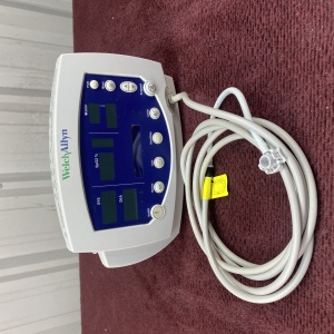
4.4 Display Control Unit (DCU)
The DCU may be used in the MR system room, MR control room, or in the MR holding area. Warnings and cautions must be observed to ensure safe use and system reliability. The DCU can be docked to the Cart or can operate independently under battery or AC mains power.
If the DCU must be located in the MR system room, it should be operated under battery power or docked to the Cart. If the DCU must be located in the MR system room and connected to AC mains, use the Power Supply P/N 989803169201 or P/N 989803168201. Additional power supplies may be purchased from your Invivo sales representative.
4.4.1 Installed on the Cart
Complete the following actions to install the DCU on the Cart:
To remove the DCU from the Cart complete the following actions:
4.4.2 Stand Alone Operation
Observe the following instructions to operate the DCU using AC power
4.5 Additional Installation Options
Additional installation options (such as those listed below) may increase operator ease of use, as the Expression DCU, Cart, and PMC are configured with input/output ports that permit connections to external equipment:
-
Connection to an external projector.
-
Connection to an external monitor.
-
Connection to facility information systems.
SYSTEM POWER‐UP
Follow the steps below to perform system power‐up and operational verification.
5.1 Removing AC Mains Power
To remove the Expression MRI Patient Monitoring System (Cart, PMC, or DCU) from AC mains power, use one of the following methods:
-
Remove the AC power cord from the AC mains outlet; or
-
Remove the DC power cord from the rear input port of the device.