Description
1.1 Scope of Manual
This manual contains detailed troubleshooting, scheduled maintenance, maintenance, and service instructions for the M7 SpeedClave ® Sterilizer. This manual
is intended to be used by Midmark’s authorized service
technicians.
1.2 How to Use Manual
A. Manual Use When Performing Scheduled Maintenance.
(1) Perform inspections and services listed in
Scheduled Maintenance Chart (Refer to
para 3.1).
(2) If a component is discovered to be faulty or out
of adjustment, replace or adjust component in
accordance with Maintenance / Service Instructions (Refer to para 4.1).
B. Manual Use When Sterilizer Is Malfunctioning And
Cause Is Unknown.
(1) Perform an operational test on sterilizer (Refer
to para 2.1).
(2) Perform troubleshooting procedures listed in
Troubleshooting Guide (Refer to para 2.2).
(3) If a component is discovered to be faulty or out
of adjustment, replace or adjust component in
accordance with Maintenance/Service Instructions (Refer to para 4.1).
C. Manual Use When Damaged Component Is Known.
(1) Replace or adjust component in accordance
with Maintenance/Service Instructions (Refer to
para 4.1).
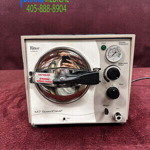
1.3 Description Of M7 Sterilizer
A. General Description (See Figure 1-1).
The M7 SpeedClave ® Sterilizer is a self generating
steam sterilizer designed to sterilize instruments and
other sterilizable goods. The major components of the
sterilizer consist of a chamber, condensing tank assembly, heating element, temperature regulator relay,
diaphragm cup, timer assembly, timer buzzer, manual
reset overheat thermostat (low water), auto-reset
overheat thermostat (low water) (auto-reset overheat
thermostat is only on newer units with CS or RB serial
number prefixes), pilot light, fill / vent valve, bellows
assembly, pressure relief valve, temperature gauge,
and reset button linkage assembly.
B. Theory of Operation (See Figures 5-1 thru 5-3).
Electrical Operation
Current flows thru the normally closed contacts of the
overheat thermostat(s) (also known as the low water
thermostat) to one side of the contacts on the timer
switch. When the timer assembly is not set to a time,
the timer switch contacts are not closed and no path to
the heating element is completed. When the operator
sets the timer assembly to any time setting, the timer
switch contacts are closed allowing current to flow
across the normally closed contacts of the temperature
regulator relay and be applied to the heating element,
causing it to heat up. Current is also applied across the
pilot light causing it to illuminate, thus indicating that the
heating element is energized. The diaphragm cup is
pressure sensitive and expands outward as the pressure in the chamber increases. The normally closed
temperature regulator relay is adjusted so the diaphragm cup will push open the contacts of the relay
when the selected temperature / pressure is reached
during a sterilizing cycle, de-energizing the heating
element. When the temperature / pressure lowers
slightly, the diaphragm cup contracts allowing the
temperature regulator relay to close its contacts which
causes current to be applied to the heating element and
pilot light again. The temperature in the chamber is
regulated to within +1° to +2° of the selected temperature during the cycle by the continuous opening and
closing of the temperature regulator relay contacts by
the diaphragm cup. The timer assembly contains a
timer motor which runs the timer assembly. When the
timer is run down to a setting of 0 minutes, the timer
switch contacts move, breaking the circuit to the
heating element and pilot light. A circuit to the timer
buzzer is now completed, causing it to sound. The
timer assembly timer motor continues to run for one
minute. Then the timer switch contacts are opened,
causing the timer buzzer to stop sounding.
During the cycle, if the temperature inside the chamber
rises up higher than 285°F (141°C), the normally closed
manual reset overheat thermostat (also known as low
water thermostat) contacts open, breaking the circuit to
the timer switch, heating element, and pilot light. The
most frequent cause of activation of the overheat
thermostat is a low water condition in the chamber. The
N.C. auto-reset overheat thermostat is a safety backup
for the manual reset overheat thermost and opens at
295°F (146°C). The manual reset overheat thermostat
is reset by pressing the RESET button located on front
panel of the sterilizer and the auto-reset overheat thermostat automatically resets after approximately six minutes.
Water / Air / Steam Flow
The M7 sterilization cycle has four phases; filling, heat
up, sterilizing, and venting.
During the fill portion of the cycle, the operator depresses the FILL / VENT lever which opens the fill /
vent valve. Water flows from the condensing tank thru
the fill / vent valve and into the chamber. When the
operator visually observes that the water level in the
chamber is within 1/2 in. to 5/8 in. (13 to 16 mm) from
the front rim of the chamber, the operator releases the
FILL / VENT lever, closing the fill / vent valve. Now the
operator begins the heat up portion of the cycle by
turning on the timer assembly.
During the heat up portion of the cycle, the water is
heated by the heating element. As the water begins to
boil, air is bled off thru the bellows assembly into the
condensing tank. When the bellows assembly senses
pure steam flowing thru it, the valve in the bellows
assembly closes, allowing pressure in the chamber to
build. The sterilizing portion of the cycle begins when
the bellows assembly is completely closed, not allowing
steam to flow thru it, and the desired temperature in the
chamber for the selected cycle is reached. The operator sets the timer assembly for the desired length of the
cycle and the cycle is run.
When the timer assembly counts down to 0 minutes
and shuts off the heating element, the vent portion of
the cycle begins. After the door handle has been
moved to the vent position, the operator depresses the
FILL / VENT lever which opens the fill / vent valve.
Steam and water flow thru the fill / vent valve and into
the condensing tank, venting the chamber. There is
coiled tubing under water in the condensing tank which
serves to turn the steam back into water.
There is a pressure relief valve which opens if the
pressure in the pressure valve reaches 31 PSI (214
kPa) during a cycle. This provides a safety relief for the
chamber so that unsafe pressures cannot build.
There is a temperature gauge on the front control panel
which indicates the temperature inside the chamber
during a cycle.
1.4 SPECIFICATIONS
Factual data for the sterilizer is provided in Table 1-1.
Table 1-1. Specifications
Description Data
Dimensions (overall):
Length ……………………………………….. 19 in (48.3 cm)
Width ………………………………………….. 14 in (35.6 cm)
Height ……………………………………………. 13 in (33 cm)
Shipping Carton ………………………… 24 in x 16 in x 16 in
(61 cm x 40.6 cm x 40.6 cm)
Door Opening ……………………………… 6 5/8 in. (16.8 cm)
Weight:
With Reservoir Empty …………………….. 30 lb (13.6 kg)
With Reservoir Full ………………………… 39 lb (17.7 kg)
With Shipping Carton ……………………… 39 lb (17.7 kg)
Water Reservoir Capacity ……………. Approx. 3/4 gallon
(2.75 Liters) to full mark
Electrical Requirements:
100 VAC Unit (M7-003) ………….. 100 VAC 50 – 60 HZ,
15 amp, single phase
115 VAC Unit (M7-001, ….. 110 – 120 VAC 50 – 60 HZ,
M7-004, and M7-005) 10 amp, single phase
230 VAC Unit (M7-002) ….. 220 – 240 VAC 50 – 60 HZ,
5 amp, single phase
Power Consumption:
100 VAC Unit ………………………………….. 1150 WATTS,
12 amps @ 100 VAC
115 VAC Unit ………………………………….. 1150 WATTS,
10 amps @ 120 VAC
230 VAC Unit ………………………………….. 1150 WATTS,
5 amps @ 240 VAC
Recommended Circuit:
A separate (dedicated) circuit is recommended for
this sterilizer. The sterilizer should not be connected
to an electrical circuit with other appliances or
equipment unless the circuit is rated for the additional load.