Description
INTENDED USE
The Wallach ZoomScope is a microscope for colposcopy. The ZoomScope has a range of
magnification from 4.66x to 20x.
INSTRUCTIONS FOR USE
-
ASSEMBLY
A. Mobile Floorstand
The stand has been sent unassembled for shipping purposes. Only one wrench is needed, and it is taped to the base along with the appropriate hardware. To complete assembly, place the scope column in the column mount hole so it is standing upright. Carefully tip the entire unit on its side. Line up the holes underneath the base with the holes in the bottom side of the column and insert the bolts. Tighten using the wrench supplied. A three-legged base is standard with the ZoomScope; a four-legged or five-legged base is optional.
(NOTE: Four and five-legged bases use one bolt.)
B. Light Box and Suspension Arm
Place the light box and suspension arm assembly on the top of the column. The hole in the bottom of the light box will fit over the column post. Be sure the white or black Teflon ring is placed over the pin on the column before mounting.
C. Microscope Head
Place the microscope head into the retaining ring. Hand-tighten the thumb screw.
Remove protective caps from the diopter rings. Gently push the eyepieces into the binocular tubes. Care should be taken to keep eyepieces in an upright position, as they will slip out if the microscope head is turned upside down.
Caution: Do not tilt head all the way back as eyepieces can slide out of the binoculars and become damaged.
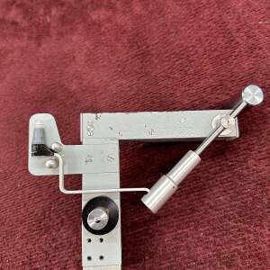
D. Installation of Optional Removable Handlebars for ZoomScope
1. Align the scope as you would to look through the Nikon head in a downward position.
2. The stainless steel mounting brackets are located on the left and right sides of the Nikon head retaining ring.
3. The corresponding handles marked “L” (left) and “R” (right) should be inserted into the mounting brackets. NOTE: The handles are marked on the solid end.
4. The holes in the middle of the retaining brackets allow for two positions:
a) Handles are parallel to the retaining ring, and
b) In a position of 90 Degrees away from this.
II. ARM ADJUSTMENT
Your Wallach ZoomScope is adjusted and tested just prior to leaving the factory. The ZoomScope arm may be moved into any position and should remain in place. However, further arm adjustments may become necessary. A 5/64 Allen wrench is included.
A. For Arm Tightening Adjustment
1. To Tighten Up & Down Motion of the Arm
Find set screws (two pair) on the long part of the arm. Tighten these thumb screws ⅛ turn at a time with a 5/64 Allen wrench by turning the screws clockwise. The arm
movement may be set to a desired tension by using these screws. All retaining screws should be tightened the same amount (refer to instruction card on column).
2. Tighten Back & Forth Motion
Find set screws on the short part of the arm. These screws should be tightened ⅛ turn at a time with a 5/64 Allen wrench by turning clockwise. The back and forth motion may
be set to a desired tension by using these screws. All set screws should be tightened the same amount.
III. OPTICAL HEAD ADJUSTMENT
A. Adjustment
The Wallach ZoomScope is two optical instruments in one. Loosen the thumb screw, reposition the head and re-tighten. Then flip the head bracket. It can be used as a colposcope or as an operating microscope.
Caution: Care should be taken to keep eyepieces in an upright position, as they will slip out if the microscope head is turned upside down.
B. Changing the Eyepieces
While holding the microscope head, gently slide the eyepieces from the binocular tubes. To replace, gently push the eyepieces back into the binocular tubes assuring that they are fully seated.
NOTE: Do not touch the lenses when handling eyepieces. Eyepieces should
be cleaned the same way as any photographic lens.
C. Magnification
Final magnification is determined by multiplying the eyepiece power times the microscope body power times the objective lens power. The Wallach ZoomScope is normally shipped with 20x eyepieces and .33x objective lens.
Therefore, at the lowest setting of the magnification power knob (0.7), the magnification would be:
20 x .7 x .33x = 4.66x power
At the highest setting of the magnification power knob (3.0) the final magnification would be:
20 x 3 x .33x = 20x power
Optional eyepieces and lenses are available to provide magnification from 1.89x to 42x. Objective lens available in .27x, .33x, .40x, .50x, and .70x.
Eyepieces available at 10x, 15x and 20x magnification.
IV. ELECTRICAL
The Wallach ZoomScope requires 110 volt AC power to operate (240 volt, 50 Hz international). It is supplied through a 2.5 meter detachable cord in standard 120 volt versions. For your safety, assure that your electrical outlets meet code regulations. The master power switch is located on the side panel of the light box assembly. This switch turns the main power source on or off. The switch on the front panel turns the light on or off. The knob on the front panel controls the light intensity.
For longer bulb life, set the light intensity at a comfortable level. Use the light at maximum intensity only when necessary. Shut off when not in use. Please note that the bulb will last longer if the dimmer switch is turned down and the fan is allowed to cool the bulb before shutting off the master power.
NOTE: If the scope is jolted or moved across a bumpy floor before the bulb has cooled, the bulb may blow out prematurely.
The replacement bulbs may be ordered from Wallach Surgical Devices (203) 799-2000, or purchased from a local camera shop. Wallach Bulb REF 906117; Tungsten Halogen Projector Lamp ESD, 150 watt, 120v.
A. Directions for Replacing the Light Bulb
1. Shut “OFF” the master switch and unplug the cord.
2. Remove the bulb cover by loosening the black screws.
3. Facing the scope, move the silver wire lever to the rear of the scope.
4. The bulb will move up. Completely remove it by hand.
5. Put the lever back in the forward position. Insert the new bulb, holding it against
the bracketing. Push it all the way in until it clicks.
B. Directions for Replacing the Fuses
1. Shut “OFF” the master switch and unplug power cord.
2. The light box contains two fuses beneath the power socket.
3. To remove, pull out the drawer beneath the power socket.
4. Remove the blown fuse from the holder and replace with a 2 amp, 5mm x 20mm Fast Blow Fuse
5. Push the fuse holder back into the light box housing.
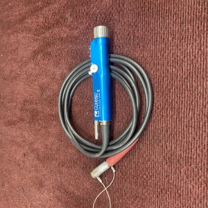
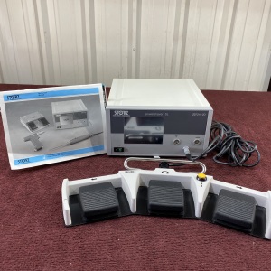
C. Directions for Attaching Footpedal (used for power options)
Attach by inserting male connector into female receptacle located at the bottom of the lamp housing.
V. SCOPE OPERATION
A. Plug in the power cord.
B. Turn “ON” Master switch.
C. Turn “ON” front panel light switch.
D. Turn power knob to appropriate light intensity. This can be adjusted at any time
during the procedure.
E. Position the ZoomScope; lock casters in place.
F. A green filter is located on the light director for diagnostic purposes. This can
easily be flipped into place during a procedure.
G. See “Focusing” instructions that follow.
VI. POSITIONING THE ZOOMSCOPE
Set the Wallach ZoomScope in front of the examination table so that one leg is
perpendicular to the table and in line with the ZoomScope suspension arm. Each leg is equipped with a locking caster. To lock the caster, push down. To unlock the caster, push up.
VII. FOCUSING THE ZOOMSCOPE
A. Turn both diopter rings on the binocular tubes until the end surface of each ring coincides with the black engraved lines.
B. Looking into the eyepieces, set the distance between the oculars to conform to your interpupillary distance by moving the binocular tubes so that both circular view fields are brought into coincidence.
C. Set the zoom knob to 3x. (If power zoom is available, the foot pedal should be used).
D. Adjust the fine focus rack to midway of travel. Position the head at approximately 305mm (for .33x objective lens) from the target to coarse focus. Rotate the fine focus knobs to bring the target into focus. The fine focus knobs can be tightened or loosened to adjust travel ease by rotating them in opposite directions. If power focus is available, the foot pedal must be used for focusing operations. Do not re-adjust fine focus after a clear image is viewed at the 3x zoom magnification.
E. Rotate the zoom knob to 0.7x (Foot Pedal should be used where power zoom is available).
F. Close your right eye; adjust the left diopter ring to bring the target into focus. Close your left eye; adjust the right diopter ring to bring the target into focus.
G. At this point, focusing has been complete. Steps A through G can be repeated for exact focusing if desired. As long as the scope is not moved out of position, or the fine focus adjustment is not moved, the target will keep its sharpness at all times regardless of the zoom magnification level.
VIII. MOVING THE ZOOMSCOPE
To move the ZoomScope from room to room, release the locking casters, unplug the power cord from the outlet and position the microscope head away from the direction of movement. Grasp the column with one hand and the scope with the other and push the ZoomScope to its new location. For added stability, it is best to position the suspension arm directly over any one of the legs as it is being moved.
IX. VIDEO ZOOMSCOPE
Analog Camera Setup
The camera is shipped next to the microscope head in the protective box. Connect the end of the cord which is attached to the suspension arm nearest to the microscope head to the camera. Connect the other end to the camera control unit (CCU) located on the side of the light box. The camera is attached to the microscope head by sliding it in the camera holder sleeve and turning the bayonet locking knob 1/8 of a turn.
To orient the image as seen through the binocular eyepieces, loosen the camera connector by disengaging the lock and rotate the black collar until the image is identical to what is being viewed. Be sure to lock the camera in place after the image has been oriented correctly.
Video Monitor (NTSC) Setup
1. Connect the “s” video cable provided from the “Video Out” port (S Video) in the back of the camera control unit (CCU) to the “Video In” (S Video) port on the monitor.
NOTE: If purchasing the NTSC video monitor from another source, be sure to match connector configurations. Adaptors for other monitors may be available from your local video supplier. (The monitor should have a minimum horizontal resolution of 420 lines).
2. If using both a monitor and a printer, connect the camera to the printer and then the printer to the Monitor. (If the monitor or printer is purchased from Wallach, the cables are included).
3. See camera operation manual for operating instructions of the camera.
Laptop Setup
The Imaging Source converter box is located above the CCU. Attach the firewire cable provided to the converter box making sure to use the strain relief devices provided. Connect the other end of the firewire cable to the laptop port also making sure to use the strain relief devices by affixing them to the laptop shelf. This will insure that unnecessary weight is put on the laptop port.
X. ZOOMSCOPE SPECIFICATIONS:
-
Overall height: 160.02cm
-
Height of column: 101.6cm (116.8cm and 139.7cm also available)
-
Overall weight: 29.48kg
-
Center of column to end of leg: 39.37cm
-
Center of column to center of microscope with boom suspended horizontally: 50.80cm Height of microscope from depressed position of suspension to floor: 67.31cm. At extreme position of suspension: 116.8cm (with short column.)
-
2.44 meter grounded power cord
-
Fused power input lamp 2.0 amps
XI. SERVICE AND REPAIR
In the event your ZoomScope becomes inoperative, please make the following checks before calling the factory:
1. Check that the unit is plugged into a working wall receptacle.
2. Check for a burned-out bulb.
3. Check for a blown fuse.
Bulb, optional eyepieces, etc. are available from the factory.
If your ZoomScope is still inoperative, call the factory at (203) 799-2000 and ask for the Repair Department.